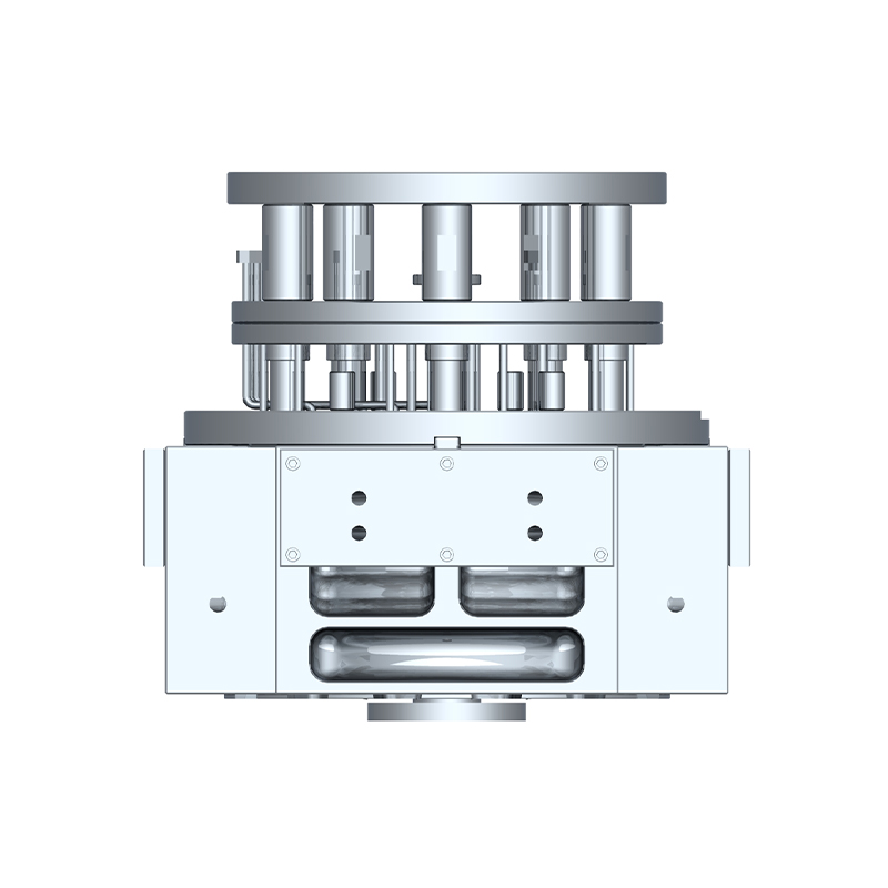
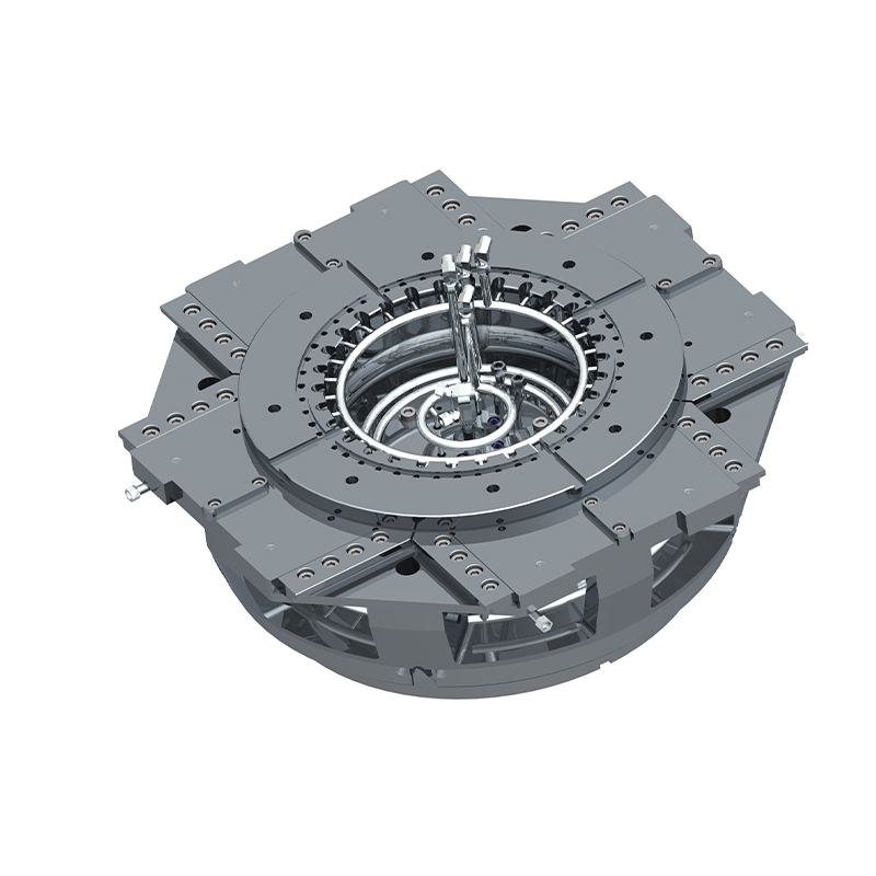
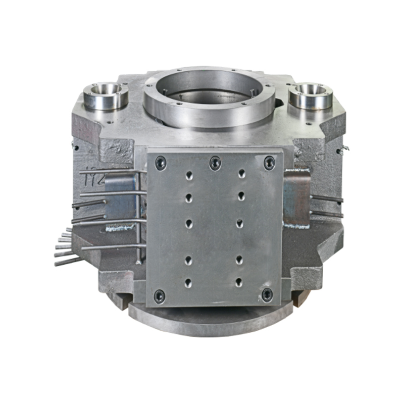
We offer molds for diverse industries, including automotive, military, and construction, enabling global competitiveness through innovation and expertise.
Key parameters and optimization methods for aluminum alloy casting mold design
Abstract
Aluminum alloys, with their low density, high specific strength, and corrosion resistance, are widely used in industries such as automotive, aviation, machinery manufacturing, and electronics. Mold design is a core component of the aluminum alloy casting process, directly determining the dimensional accuracy, surface quality, and production efficiency of the castings.
1. Introduction
Aluminum alloy casting is widely used in the manufacture of lightweight structural parts such as automotive engine blocks, transmission housings, aviation components, and electronic enclosures. With the increasing market demand for high-quality aluminum alloy castings, traditional empirical mold design has gradually evolved towards digitalization, refinement, and intelligentization.
Molds not only directly shape the molten aluminum but also must withstand high-temperature erosion, thermal fatigue cycles, and mechanical wear. Therefore, proper design is crucial to reducing defects such as porosity, cold shuts, and shrinkage, and to extending mold life.
2. Key Parameters in Mold Design
2.1 Mold Material Selection
Common Mold Steels: Hot work mold steels such as H13 (4Cr5MoSiV1) and 8407 (modified H13) are commonly used for aluminum alloy die-casting molds. They are characterized by high heat resistance, high strength, good thermal fatigue resistance, and machinability.
Heat Treatment Process: Through quenching and tempering (quenching + tempering), a hardness suitable for aluminum alloy die-casting (generally 44-48 HRC) can be achieved, ensuring sufficient toughness even at high temperatures.
Performance Parameters:
Thermal Conductivity: Determines mold temperature uniformity and cooling efficiency
Coefficient of Thermal Expansion: Affects mold dimensional stability
Thermal Fatigue Resistance: Prevents cracking caused by temperature fluctuations
Material Defect Control: High steel purity is required to minimize inclusions and prevent crack sources.
2.2 Gating System Design
Gate Location: Appropriate gate location shortens the filling path, reduces oxide inclusions and porosity defects, and avoids cold shuts. Gate Shape and Cross-Section: Scalloped, rectangular, or semicircular gates are commonly used. The cross-section size must match the aluminum liquid flow rate. Excessively large gates can easily cause scouring, while too small can easily form cold shuts.
Runner and Cross-Runner Design: The filling time of each cavity must be balanced to prevent turbulent aluminum flow. The cross-section ratio is typically 1:2:1.5 for straight runner:cross runner:gate.
Filling Time and Speed Control: In die casting, the filling time is generally controlled between 0.04 and 0.08 seconds to ensure that the cavity is fully filled with aluminum liquid before solidification.
2.3 Cooling and Temperature Control System
Cooling Channel Layout: Cooling channels should be placed as close as possible to hot spots (such as thick walls and near the gate), but should avoid weakening the mold.
Local Cooling Technology: High-thermal conductivity inserts or heat pipes can be used in thick-walled areas to enhance cooling and prevent shrinkage cavities.
Temperature Control Equipment: A mold temperature controller stabilizes the mold temperature to prevent cracks caused by excessive temperature fluctuations. Temperature Monitoring: Thermocouples are installed at key locations for real-time monitoring and closed-loop control.
2.4 Venting and Overflow System
Vent Hole Design: Vent holes are typically 0.30.5 mm wide and 0.020.05 mm deep, ensuring smooth gas discharge without splashing molten aluminum.
Overflow Trough: Collects oxide film and cold molten metal that first enters the mold cavity, preventing defects from entering the main casting.
Vacuum-Assisted Technology: For high-demand castings (such as automotive structural parts), vacuum pumps can be used to further reduce pores.
3. Design Optimization Methods
3.1 Optimization Based on CAE Simulation
Filling Simulation: Utilize software such as ProCAST and MAGMASoft to predict the flow path and temperature distribution of molten aluminum and optimize gate location and size.
Solidification Analysis: Determine the solidification sequence to avoid shrinkage and hot spots.
Parameter Iteration: Based on simulation results, adjust the cooling channel diameter, layout, and flow rate to achieve balanced mold temperature. 3.2 Modular and Replaceable Component Design
Core inserts, such as the cavity block, inserts, and sprue bushings, can be replaced individually, reducing the cost of replacing the entire mold.
Maintenance: The modular structure facilitates quick repair of cracks and worn areas, minimizing downtime.
3.3 Surface Treatment and Coating Technology
Nitriding: Improves mold surface hardness and wear resistance, reducing sticking.
PVD/CVD coatings, such as TiN and CrN, significantly enhance thermal fatigue resistance and corrosion resistance.
Surface polishing and shot peening: Improve surface roughness and reduce crack initiation points.
4. Case Study
Take a die-casting mold for an automobile engine housing as an example:
Pre-optimization issues: High porosity (approximately 8%), significant cold shut defects, and a mold life of only 65,000 cycles. Optimization Measures:
Adjusted gate position and optimized runner cross-section ratio;
Added high-thermal conductivity inserts in thick-walled areas to enhance cooling;
Introduced a vacuum-assisted exhaust system;
Applied TiN coating to the cavity surface.
Optimization Results:
Porosity reduced to below 2%; Cold shut defects eliminated; Mold life increased to 95,000 cycles; First-pass yield of finished products increased to 97%.

 English
 中文简体
中文简体